Contract composite manufacturing services
Five stages, all of them here: design, prototyping, tooling, layup and finishing. Process routes, material options and limits are all listed below.
CAD, engineering and design
Send a model, a drawing or a sample part. What comes back is geometry that can be moulded and a laminate schedule to build it to.
Geometry can reach us as a STEP or IGES model, as a dimensioned drawing, or as a physical part we reverse engineer. We work through the features that decide whether a part can be moulded at all — draft angle, where the split line falls, how the edges close out, where inserts and fixings sit — and we set the laminate schedule and fibre orientation against the load case. Nothing goes to tooling until the geometry is signed off.
- CAD modelling from drawing, sketch or physical part
- Design-for-manufacture review of supplied geometry
- Laminate schedule and fibre orientation to the load case
- Draft angle, split line and edge closeout resolution
- Insert, fixing and bonded-joint detailing
Prototyping and product development
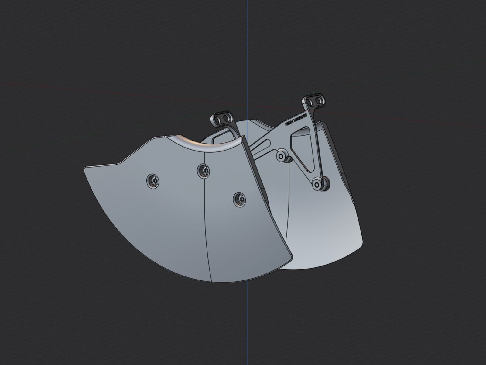
We check fit and form against the real mating part before any tool material is cut.
A dimensional error found at prototype stage costs a print. The same error found after tooling costs a tool. So where fit matters, we print an FDM prototype and check it against the actual mating surface, and we build the jigs and fixtures the production run will need at the same stage rather than improvising them later.
- 3D printing for form and fit verification
- Rapid prototyping ahead of tool commitment
- Jigs and fixtures for bonding and assembly
- Mould plugs and patterns
Composite tooling and moulds
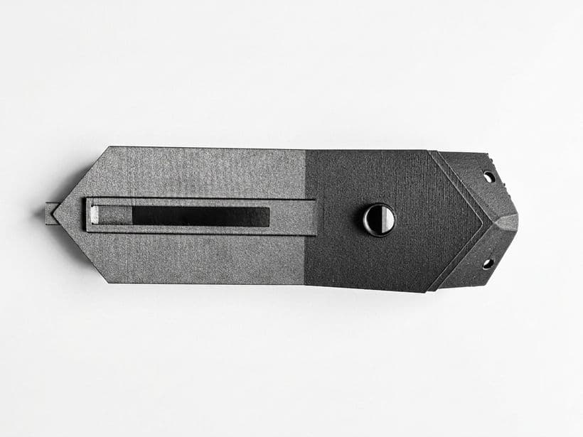
We lay fibreglass moulds on plugs taken from the approved model, and we keep the tools between runs.
Whatever state the tool surface is in transfers to every part pulled off it, so tooling decides both surface quality and how long a first order takes. We build a tool against the pull count it is expected to see — a tool for a 40-part run is not built the same way as one for 800 — and we use split and multi-part tools where the geometry closes on itself. Tools are stored here, so a repeat order re-enters the sequence at layup.
- Fibreglass moulds, taken from the approved part model
- 3D-printed mould plugs
- Tooling-board plugs, outsourced where geometry requires
- Split and multi-part tools for closed geometry
- Tool storage between production runs
Manufacturing: vacuum infusion and wet layup
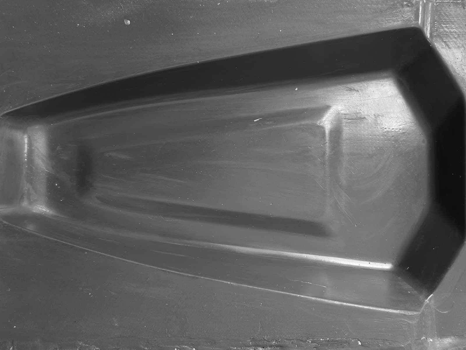
Series production to a written ply schedule held under revision, 10 to 1000 parts a year.
Vacuum infusion draws resin through a dry preform under full vacuum. Fibre volume fraction and void content come out of the process rather than out of operator technique, which is what makes one part match the next across a batch, and across a repeat order a year later. We specify wet layup under vacuum where tooling cost dominates unit cost, or where the geometry does not justify infusion. Both run to a written ply schedule held under revision.
- Vacuum infusion, for consistency across a production batch
- Wet layup with vacuum bagging, for lower quantities
- Written, revision-controlled ply schedules
- Batch range 10 to 1000 parts per year
Finishing and assembly
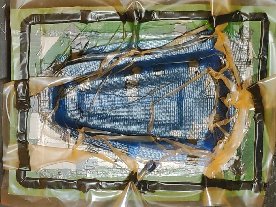
Trimming, surface preparation, coating, paint and assembly all happen here. Parts ship finished.
The defects that show in a visible laminate — pinholes, print-through — get dealt with in preparation rather than painted over in the coating. Trimming is to the drawing. Bonded hardware and assembly go on the fixtures built at prototype stage. Every part is checked against the drawing before it leaves, and nothing sits in a queue at a third party.
- Surface preparation
- Trimming to drawing
- Clear coating, gloss or satin
- Paint to supplied colour reference
- Assembly and bonded hardware
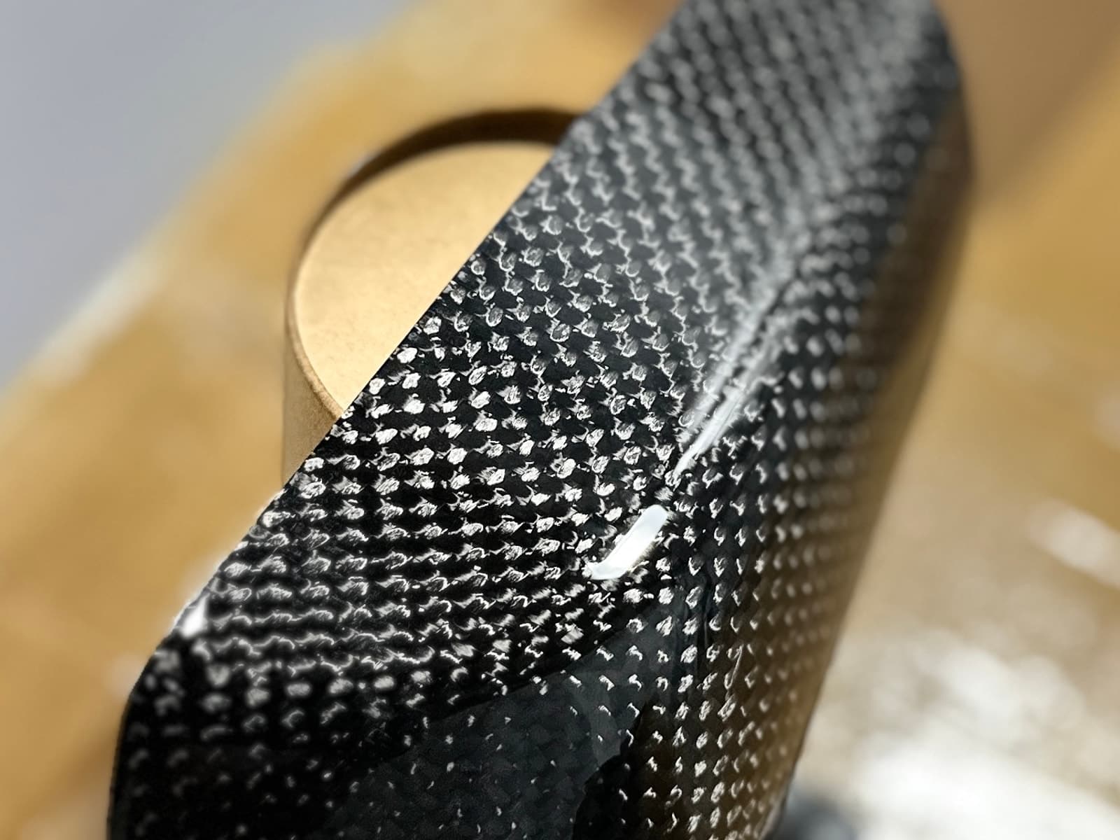
Materials: carbon fibre, aramid and glass.
We select reinforcement against the load case and the failure mode the part has to have. Form and application for each are listed below.
| Material | Form | Used for |
|---|---|---|
| Carbon fibre | 2x2 twill, plain weave | Stiffness-driven parts and visible-weave surfaces |
| Aramid (Kevlar) | Woven cloth | Impact absorption. It deforms and abrades rather than failing brittle |
| Carbon / aramid hybrid | Hybrid weave | Where both stiffness and impact tolerance are required |
| Fibreglass | Woven cloth, chopped strand | Mould tooling, and parts where cost governs and mass does not |
Kevlar and aramid parts manufacturing.
Carbon laminates fail brittle. Aramid deforms and abrades under impact and retains integrity after loading that would crack a carbon panel of equivalent thickness. Where the function of the part is protection, that failure mode governs material selection, not areal weight.
Carbon-aramid hybrid weaves are specified where stiffness and impact tolerance are both required in the same laminate. Aramid is handled here as a standard reinforcement rather than as an exception.
- Skid plates and underbody guards
- Chain guards and impact panels
- Protective housings and enclosures
- Bodywork that has to survive contact
- Carbon and Kevlar hybrid trim
Who we take contract composite manufacturing work from.
Motorsport
Race, rally and track programmes, where batches are small, revisions land mid-season and the deadline does not move. Bodywork, aero surfaces, ducting and interior panels.
Automotive
Restomod, tuning, aftermarket and low-volume vehicle programmes, including EV startups that need series parts rather than one-offs.
Industrial
Enclosures, guards and lightweight moving components. Same processes and the same tooling route as everything else we run.
Send geometry. Receive price, route and date.
We run 10 to 1000 parts a year and reply within one working day. If a part falls outside our process route or our envelope, we will tell you rather than quote it anyway.